


Honeywell
📢 100% genuine, extensive in-stock inventory, fast shipping!
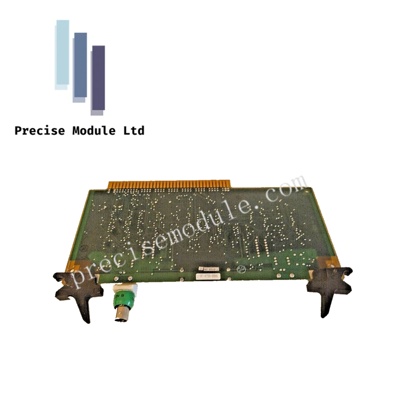
51305072-700 | Honeywell | TDC 3000 Input Output Board
51305072-700 | Honeywell | TDC 3000 Input Output Board
Manufacturer: Honeywell
-
Product No.: 51305072-700
Condition:in Stock
Product Type: Input Output Board
-
Product Origin: USA
Payment:T/T, Western Union
-
Weight: 160g
Shipping port: Shanghai/Yiwu/Shenzhen
Warranty: 12 months
Share
Honeywell 51305072-700 TDC 3000 Input Output Board
The Honeywell 51305072-700, also cataloged as the CLCN-A/B I/O short face-plate PWA, operates as a dual-channel Local Control Network (LCN) interface card for Honeywell TDC 3000 and Experion PKS systems.
Hardware Specifications
| Parameter | Specification |
|---|---|
| Model | 51305072-700 |
| Brand | Honeywell |
| Origin | USA |
| Weight | ~0.16 kg |
| Dimensions | 3.0 cm x 13.5 cm x 23.7 cm |
| Operating Temp | 0 to +60 deg C |
| Power Consumption | 12–24 VDC input, nominal 24 VDC |
| Core Performance | Dual BNC tee connectors, hot-disconnection capability, CE compliant |
Backplane Bus Communication and Profinet/EtherNet-IP Deterministic Networks
The 51305072-700 card provides deterministic backplane bus communication velocity across dual LCN paths (Cable A and Cable B). Integrated BNC tee connectors allow seamless insertion or removal of nodes without interrupting communication across active segments. The short face-plate variant is designed for secondary expansion rows, ensuring compatibility with multi-slot chassis assemblies. Electrical isolation up to 1500 VDC protects against industrial interference and fault conditions.
Frequently Asked Questions
Q: Can the 51305072-700 be disconnected while the LCN is live? A: Yes, the front-mounted BNC tee connectors allow hot-disconnection without disrupting communication across remaining nodes.
Q: What chassis slots are supported? A: The module fits standard 5-slot and 10-slot chassis assemblies, excluding Slot 1.
Q: How does the card achieve redundancy? A: Dual coaxial routing supports A/B channel redundancy, ensuring fault-tolerant communication.
Field Installation Guidelines
- Insert the card into designated chassis slots with full connector engagement.
- Ensure BNC tee connectors are properly seated and shielded to prevent signal reflection.
- Maintain grounding continuity for shielding layers to minimize electromagnetic interference.
- Route coaxial cabling separately from high-voltage conductors.
- Verify redundant A/B path integrity during commissioning before enabling system operation.
Hot Tags :


- Choosing a selection results in a full page refresh.
- Opens in a new window.