


Bently Nevada
📢 100% genuine, extensive in-stock inventory, fast shipping!
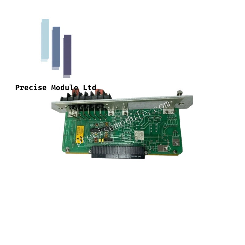
Bently Nevada 125740-01 Tachometer Monitor I/O Module
Bently Nevada 125740-01 Tachometer Monitor I/O Module
Manufacturer: Bently Nevada
Condition:in Stock
Product Type: Tachometer Monitor I/O Module
-
Product Origin: USA
Payment:T/T, Western Union
-
Weight: 360g
Shipping port: Shanghai/Yiwu/Shenzhen
Warranty: 12 months
Share
Bently Nevada 125740-01 Tachometer Monitor I/O Module
The Bently Nevada 125740-01 is the rear Input/Output (I/O) module designed for the 3500/50 Tachometer Monitor. Located at the back of the 3500 chassis, this module provides the physical terminal interfaces to receive pulses from Keyphasor transducers, proximity probes, or magnetic pickups to measure rotational speed, phase, and acceleration.
Hardware Specifications
| Parameter | Specification |
|---|---|
| Part Number | 125740-01 |
| Associated Module | 3500/50 Tachometer Monitor |
| Connection Style | Internal Terminations (Accepts direct wire-to-lug field connections) |
| Terminal Capacity | 0.2 to 1.5 mm² (16 to 24 AWG) multi-strand or solid shielded industrial wire |
| Weight | 0.36 kg (0.79 lbs) |
| Dimensions | 240 mm × 25.4 mm × 241 mm (9.45 in × 1.00 in × 9.50 in) |
| Operating Temperature | -30°C to +65°C (-22°F to +150°F) |
| Power Consumption | Passive routing and line conditioning (< 1.5 Watts drawn from rack) |
| Isolation Strength | 500 Vrms galvanic isolation between field inputs and the rack backplane |
| Rack Allocation | Installs into the upper or lower rear slots directly behind the 3500/50 main card |
| Compliance | Fully compliant with API 670 machinery protection standards |
Operational Functionality
The 125740-01 rear I/O module processes speed-related trigger pulses before routing them to the front-facing 3500/50 main card. It supports several turbine protection applications:
- Standard Tachometer: Tracks absolute rotor speed (RPM) and rotor acceleration trends.
- Reverse Rotation Detection: Verifies that the turbine shaft does not spin backwards during shutdown, preventing severe auxiliary pump or seal damage.
- Zero Speed Tracking: Safely monitors low-frequency shaft movements down to 0 Hz, validating when a turbine has come to a complete stop before turning gear engagement.
- High-Temperature Compatibility: Frequently paired with Bently Nevada’s 3300 High-Temperature Proximity System (HTPS). This system routes speed and phase trigger signals out of extreme thermal zones—such as near labyrinth steam seals, turbine exhaust paths, and strut-supported hot bearings—and routes them safely into the 125740-01 terminals.
Galvanic Protection Shielding: The module incorporates built-in 500 Vrms isolation circuitry. If a high-voltage spike occurs on the field wiring side, the onboard isolation barriers absorb the energy, preventing electrical faults from damaging the expensive internal bus of the 3500 system rack.
Frequently Asked Questions
Q: Can this I/O module accept input from both active magnetic pickups and passive proximity sensors?
A: Yes. The 125740-01 is fully configurable to interface with passive proximity probes (like the 3300 XL series), active magnetic pickups, or optical speed sensors. These parameters are assigned within the 3500 Rack Configuration Software.
Q: What is the difference between "Internal Terminations" and "External Terminations"?
A: "Internal Terminations" (like the 125740-01) mean that the field sensor wires land directly onto terminal strips located right on the module's PCB faceplate. "External Terminations" route the backplane connections via a multi-pin cable to a separate DIN-rail terminal block mounted elsewhere in the cabinet.
Q: Does replacing the 125740-01 rear I/O card require powering down the entire 3500 rack?
A: No. The rear I/O modules can be hot-swapped while the rack is powered. However, disconnecting this module will interrupt the active speed monitoring loop. Ensure that any automatic safety trip logic based on speed or Keyphasor data is bypassed or inhibited first.
Field Installation Guidelines
1.Inhibit overspeed trip relays:Prepare the system.
Before disconnecting the tachometer connections, place any overspeed or zero-speed safety interlocks linked to this card into Bypass to prevent an automated system trip.
2.Disconnect field wires:Clean terminal layout.
Label and disconnect the individual sensor wires from the green terminal block plug on the card faceplate.
3.Remove the old rear I/O card:Unscrew chassis retainers.
Unscrew the captive screws holding the I/O card faceplate to the rack frame, then gently pull the card straight out of the slot.
4.Insert the new 125740-01 card:Align guide pins.
Slide the new card into the guide rails at the back of the rack until it seats firmly into the backplane connector. Hand-tighten the captive screws.
5.Plug in wire terminal block:Restore sensor connection.
Reinsert the wired green terminal blocks into the socket connectors, verify that the OK LED on the front 3500/50 card lights up, and remove the safety bypasses.
Hot Tags :


- Choosing a selection results in a full page refresh.
- Opens in a new window.