


Bently Nevada
📢 100% genuine, extensive in-stock inventory, fast shipping!
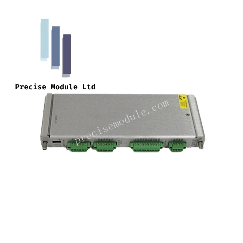
Bently Nevada 133396-01 Overspeed Detection I/O Module
Bently Nevada 133396-01 Overspeed Detection I/O Module
Manufacturer: Bently Nevada
Condition:in Stock
Product Type: Overspeed Detection I/O Module
-
Product Origin: USA
Payment:T/T, Western Union
-
Weight: 500g
Shipping port: Shanghai/Yiwu/Shenzhen
Warranty: 12 months
Share
Bently Nevada 133396-01 Overspeed Detection I/O Module
The Bently Nevada 133396-01, also cataloged as the 133396-01 Overspeed Detection I/O Module, operates as a dedicated hardware component for overspeed signal acquisition and protective output processing within the Bently Nevada 3500 machinery monitoring system.
Hardware Specifications
| Parameter | Specification |
|---|---|
| Model | 133396-01 |
| Brand | Bently Nevada |
| Origin | USA |
| Weight | 0.45 kg |
| Dimensions | 2.5 cm x 11 cm x 24 cm |
| Module Type | Overspeed Detection I/O Module |
| Transducer Power Supply | -24 VDC, 40 mA maximum |
| Power Consumption | 4 W typical |
| Recorder Output | +4 to +20 mA |
| Accuracy | +/-0.1 % of reading |
| Response Time | < 50 ms |
| Isolation | 500 VDC |
| Environmental Sealing | Epoxy sealed |
Rotor Dynamics Overspeed Signal Processing
The 133396-01 Overspeed Detection I/O Module provides signal acquisition and output functions for the Bently Nevada 3500 Electronic Overspeed Detection System. The module interfaces with speed transducers to support overspeed protection applications requiring rapid response to shaft speed changes.
The module supports redundant overspeed architectures using multiple 3500/53 modules configured in either 2-out-of-2 or 2-out-of-3 voting arrangements. The 2-out-of-3 configuration provides continuous comparison of redundant speed measurements for protective decision processing.
A conditioned 4-20 mA recorder output is available for external monitoring equipment. The module also supplies regulated transducer power for compatible speed sensing devices and provides electrical isolation between field wiring and system electronics.
The Electronic Overspeed Detection System is designed for installation in a 3500 rack equipped with redundant power supplies.
Frequently Asked Questions
Q: What voting architectures are supported by the 133396-01 module?
A: The module supports 2-out-of-2 and 2-out-of-3 voting configurations when used with compatible 3500/53 modules.
Q: What output signal is available for external recording devices?
A: The module provides a +4 to +20 mA recorder output.
Q: Does the module provide power for connected transducers?
A: Yes. The module supplies -24 VDC transducer power with a maximum output current of 40 mA.
Field Installation Guidelines
Install the 133396-01 module in the designated 3500 rack position and verify correct engagement with the backplane connector before applying power.
Use shielded transducer cables and terminate cable shields according to the system grounding requirements. Route transducer wiring separately from power cables and switching circuits to minimize electrical interference.
Verify transducer power wiring, recorder output connections, and redundant channel assignments before commissioning the overspeed protection system.
For redundant overspeed applications, confirm that the 3500 rack is equipped with redundant power supplies and that the configured voting logic matches the system protection requirements.
View full details


- Choosing a selection results in a full page refresh.
- Opens in a new window.