


Bently Nevada
📢 100% genuine, extensive in-stock inventory, fast shipping!
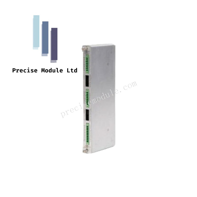
Bently Nevada 176499-01 Proximitor Monitor
Bently Nevada 176499-01 Proximitor Monitor
Manufacturer: Bently Nevada
Condition:in Stock
Product Type: Proximitor Monitor
-
Product Origin: USA
Payment:T/T, Western Union
-
Weight: 820g
Shipping port: Shanghai/Yiwu/Shenzhen
Warranty: 12 months
Share
Bently Nevada 176499-01 Proximitor Monitor
Configured for machinery protection in 3500 series platforms, the Bently Nevada 176499-01 (176499-01 Proximitor Monitor) provides direct physical signal processing and alarm evaluation for proximity transducers.
Suffix Breakdown & Model Matrix
| Option Code | Parameter | Description / Standard Specifications |
|---|---|---|
| 3500/42M | Base Model | Proximitor Seismic Monitor (Four-channel machinery protection module) |
| 176499-01 | Spare Component | Main 3500/42M Processing Card Assembly (Standard high-performance version) (Selected) |
Hardware Specifications
| Parameter | Specification |
|---|---|
| Model | 176499-01 |
| Brand | Bently Nevada |
| Origin | USA |
| Weight | 0.82 kg |
| Dimensions | 241.3 mm x 24.4 mm x 241.8 mm |
| Operating Temp | -30 to +65 deg C |
| Power Consumption | 7.7 Watts typical (7.0 Watts minimum base dissipation draw) |
| Signal Processing | 24-bit A/D digital conversion resolution per single channel input |
| Frequency Response | 0.5 Hz to 4.0 kHz (Proximitor inputs) | 1.0 Hz to 10.0 kHz (Seismic accelerometer loops) |
| Input Impedance | 10 kΩ nominal differential or single-ended transducer interfaces |
| Buffered Outputs | 4 coaxial front-panel BNC connectors (short-circuit protected, 50 Ω impedance output) |
| Accuracy | Within ±1.0% of full-scale value across the active operating temperature spectrum |
Proximitor Transducer Interface and Rotor Dynamics Processing
The 176499-01 card conditions eddy-current signal inputs to compute key static variables—such as radial vibration, eccentricity, REBAM, thrust position, and differential expansion. High-resolution 24-bit A/D converters capture the high-frequency voltage fluctuations generated by the probe's RF field. Internal digital signal processors then compare these static values against independent Alert and Danger setpoints. If configured thresholds are crossed, the card commands downstream backplane relays to execute fail-safe machinery shutdown sequences.
Frequently Asked Questions
Q: Can the 176499-01 processing module be replaced while the 3500 rack is powered? A: Yes. The main 176499-01 processor card supports hot-swap maintenance. System operators must first bypass or inhibit all active alarms on the designated slot in the 3500 Rack Configuration Software to prevent false trips during physical module extraction.
Q: What function do the front-panel coaxial BNC connectors perform? A: The four front-panel BNC outputs provide buffered, short-circuit-protected raw analog signals directly from each input channel. These 50 Ω ports allow maintenance personnel to connect portable vibration analyzers or oscilloscopes for rotor dynamic diagnosis without interrupting the machine protection system.
Q: Does the 176499-01 support seismic transducer inputs in addition to proximity probes? A: Yes. Because the 176499-01 is the internal processing card for the standard 3500/42M module, its software-configurable channels can process seismic accelerometer and velocity sensor signals alongside standard Proximitor loops.
Field Installation Guidelines
- Seat the Processing Card: Slide the 176499-01 card into the selected front slot of the 3500 chassis. Ensure the edge connector fully engages the backplane before securing the top and bottom captive screws to 0.9 N-m.
- Observe Temperature Dissipation: Do not block ventilation pathways on the rack enclosure. The unit dissipates up to 7.7 Watts of thermal energy under full diagnostic load; verify cabinet operating temperatures remain below +65 deg C.
- Verify I/O Module Matching: Confirm that the rear-mounted I/O termination module matches the expected configuration of the front-slot processor. Any physical mismatch will trigger a slot configuration error LED on the main card.
- Shield External Cable Noise: Terminate all coaxial probe extension shields at the rear I/O terminal strip ground points. Keep the transducer lines separate from high-voltage motor or generator power lines to suppress electromagnetic interference.
Hot Tags :


- Choosing a selection results in a full page refresh.
- Opens in a new window.