


Bently Nevada
📢 100% genuine, extensive in-stock inventory, fast shipping!
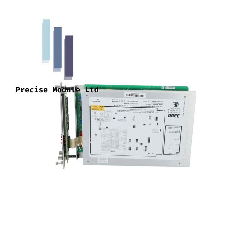
Bently Nevada 3300/45-XX-01-03-00 Position Monitor
Bently Nevada 3300/45-XX-01-03-00 Position Monitor
Manufacturer: Bently Nevada
Condition:in Stock
Product Type: Position Monitor
-
Product Origin: USA
Payment:T/T, Western Union
-
Weight: 1420g
Shipping port: Shanghai/Yiwu/Shenzhen
Warranty: 12 months
Share
Bently Nevada 3300/45-XX-01-03-00 Position Monitor
The Bently Nevada 3300/45-XX-01-03-00, also cataloged as the 3300/45 Position Monitor, operates as a dedicated hardware component for dual-channel axial position and differential expansion measurement within Bently Nevada 3300 Machinery Protection System platforms.
Suffix Breakdown & Model Matrix
| Option Code | Parameter | Description / Standard Specifications |
|---|---|---|
| 3300/45 | Base Model | Position Monitor (2-Channel) |
| XX | Transducer Input | Configurable: Select based on your probe system type (e.g., -01, -02) |
| 01 | Frequency Range | 0.4 Hz to 100 Hz (Standard for slow axial displacement) |
| 03 | Relay Logic | Hermetically sealed alarm/trip relays |
| 00 | Agency Approval | None Required / Standard industrial safe-area |
Hardware Specifications
| Parameter | Specification |
|---|---|
| Model | 3300/45-XX-01-03-00 |
| Brand | Bently Nevada |
| Channels | 2 Independent channels |
| Input Type | Proximity sensor |
| Frequency Response | 0.4 Hz to 100 Hz |
| Operating Temp | 0 deg C to +65 deg C |
| Recorder Outputs | +4 to +20 mA or -10 Vdc |
Mechanical Monitoring & TSI Integration
The 3300/45 provides critical data for shaft position monitoring by maintaining accurate eddy-current probe scaling. To ensure reliable machinery protection, the module requires periodic gap voltage validation, typically centered at -10 VDC, to maintain linearity during axial shaft migration. The architecture includes cross-talk suppression circuits to isolate the dual channels from signal interference, facilitating precise detection of rotor displacement and expansion in heavy-duty turbomachinery while minimizing nuisance trips.
Frequently Asked Questions
Q: Why is the frequency response limited to 100 Hz?
A: This frequency range is optimized for axial position and differential expansion measurements, where the mechanical movement of the shaft or casing occurs at relatively low frequencies compared to radial vibration.
Q: Can the recorder outputs be configured for both current and voltage?
A: Yes, the module supports configurable output signals, allowing integration with external recorders or control systems using either 4-20 mA current loops or -10 Vdc voltage signals.
Field Installation Guidelines
- Slot Mounting: Insert the module into the 3300 instrument rack. Ensure backplane pins are aligned to prevent damage to the serial data bus and power connections.
- Probe Setup: Connect the proximity transducers using shielded coaxial cabling. Verify the probe tip distance corresponds to the calibrated gap voltage for the specific transducer type designated by the XX suffix.
- Relay Logic: Configure the alarm/trip setpoints via the rack interface to match the mechanical clearance limits of the turbine or compressor being monitored.
- Verification: Utilize the dual 63-segment LED bargraphs on the front panel to monitor real-time position data and confirm proper signal response during machine operation.
Hot Tags :


- Choosing a selection results in a full page refresh.
- Opens in a new window.