


Bently Nevada
📢 100% genuine, extensive in-stock inventory, fast shipping!
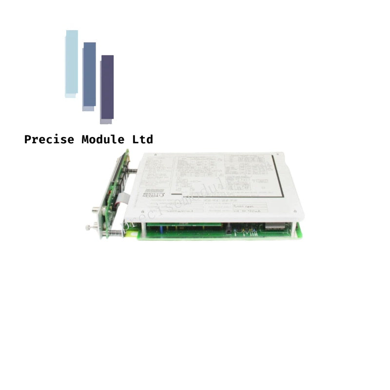
Bently Nevada 3300/50 3300 System Tachometer Monitor
Bently Nevada 3300/50 3300 System Tachometer Monitor
Manufacturer: Bently Nevada
Condition:in Stock
Product Type: Tachometer Monitor
-
Product Origin: USA
Payment:T/T, Western Union
-
Weight: 1500g
Shipping port: Shanghai/Yiwu/Shenzhen
Warranty: 12 months
Share
Bently Nevada 3300/50 3300 System Tachometer Monitor
The Bently Nevada 3300/50, also cataloged as the 3300/50 Tachometer Monitor, operates as a dedicated hardware component for measuring shaft rotative speed, rotative acceleration, or zero speed indication within Bently Nevada 3300 Machinery Monitoring platforms. The single-channel instrument accepts electrical pulse inputs from up to two separate speed transducers, executing internal voting logic to ensure precise speed measurements and protective alerting while minimizing the risk of false trips in the event of a single sensor failure.
Hardware Specifications
| Parameter | Specification |
|---|---|
| Model | 3300/50 |
| Brand | Bently Nevada |
| Origin | USA |
| Weight | 1.5 kg |
| Dimensions | 5.1 x 20.3 x 30.5 cm |
| Operating Temp | 0 to +65 deg C |
| Storage Temp | -40 to +85 deg C |
| Input Impedance | 10 kOhm |
| Output Impedance | 100 Ohm |
| Duty Cycle | 1 percent minimum |
| Relative Humidity | To 95 percent, non-condensing |
Machinery Monitoring & TSI Features
The Bently Nevada 3300/50 executes real-time speed tracking and acceleration calculations to detect machine overspeed or underspeed states. Designed for rotor dynamics monitoring, the module operates as an integral part of Turbine Supervisory Instrumentation (TSI), supporting Keyphasor proximity probe inputs or magnetic pickup sensors. To suppress high-frequency signal cross-talk across the 3300 backplane, the tachometer uses internal hardware filters that isolate pulse-train trigger signals from sensitive analog vibration channels. The module supports zero speed indication to prevent early turning gear engagement and ensures correct gap voltage validation when utilizing proximity-type speed sensors.
Frequently Asked Questions
Q: How does the dual-transducer voting logic operate within this single-channel monitor?
A: The 3300/50 continuously monitors the health (OK status) of both speed transducers. If both sensors are functioning normally, the monitor compares their pulse rates. If one transducer fails (e.g., due to an open/short circuit), the internal voting logic automatically switches to the remaining healthy transducer, preventing a false zero-speed trip or loss of speed indication.
Q: What types of analog and digital outputs are provided on the rear terminal block?
A: The rear terminal block provides a proportional DC voltage or current output (typically representing rotative speed or acceleration) for transmission to strip chart recorders, DCS, or PLC systems. Additionally, it provides discrete Alert and Danger relay contacts for integration into external machinery protection or alarm annunciator loops.
Field Installation Guidelines
- Sensor Threshold Tuning: Set the trigger threshold levels (hysteresis) to match the voltage swing of the field transducers (such as magnetic pickups or proximity sensors) to prevent false double-triggering on shaft surface irregularities or electrical noise.
- Shield Grounding Rules: Terminate the shield wires of both speed sensors strictly at the dedicated grounding terminals on the rear Signal Input/Relay Module. Keep the shield isolated and ungrounded at the sensor end to avoid ground loops.
- Keyphasor Alignment: When using proximity probes for speed triggering, ensure the physical probe aligns precisely with the center of the shaft keyway or projection, verifying that the nominal probe gap voltage sits within the linear calibration zone.
Hot Tags :


- Choosing a selection results in a full page refresh.
- Opens in a new window.