


Bently Nevada
📢 100% genuine, extensive in-stock inventory, fast shipping!
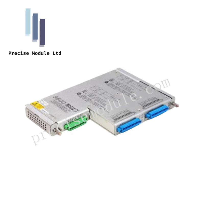
Bently Nevada 3500/40 135489-04 I/O Modules
Bently Nevada 3500/40 135489-04 I/O Modules
Manufacturer: Bently Nevada
Condition:in Stock
Product Type: I/O Modules
-
Product Origin: USA
Payment:T/T, Western Union
-
Weight: 940g
Shipping port: Shanghai/Yiwu/Shenzhen
Warranty: 12 months
Share
Bently Nevada 3500/40 135489-04 I/O Modules
The Bently Nevada 3500/40, also cataloged as the 135489-04 I/O Module, operates as a dedicated hardware component for signal routing and proximity transducer termination within the 3500 Machinery Protection System platform.
Hardware Specifications
| Parameter | Specification |
|---|---|
| Model | 3500/40 (135489-04) |
| Brand | Bently Nevada |
| Origin | USA |
| Weight | 0.94 kg |
| Dimensions | 2.5 x 18.5 x 24.1 cm |
| Operating Temp | -30 deg C to +65 deg C |
| Rack Supply | +24 Vdc |
| Power Dissipation | < 2 W |
| Full-Scale Range | 0-20 mA |
| Input Impedance | > 100 kohm |
| Protection | Over-voltage +/-30 V |
| Isolation | 1500 Vdc channel-to-ground |
Rotor Dynamics and Gap Voltage Validation
Operating within the framework of machinery protection architecture, this rear I/O module interfaces directly with proximity transducers to route raw vibration and position signals to the associated front monitor module. The internal circuitry manages eddy-current probe scaling and maintains strict gap voltage validation targets across all four input channels. Signal integrity is preserved through robust shielding and backplane routing, suppressing electrical cross-talk and supporting precise evaluation of radial vibration, thrust position, and rotor dynamics.
Frequently Asked Questions
Q: Can the 135489-04 I/O module be replaced without powering down the entire 3500 rack?
A: Yes, rear I/O modules support hot-insertion and removal when executed in coordination with front monitor slot protocols, provided proper safety measures for live industrial maintenance are followed.
Q: How are transducer signals terminated and protected against noise interference?
A: Termination is handled directly via dedicated terminal blocks on the module, utilizing standard shielding practices to ground incoming signal cables and prevent electromagnetic interference.
Field Installation Guidelines
Physical Placement: Mount the module into the designated rear slot directly aligned with its corresponding 3500/40M front monitor module within the rack frame.
Wiring and Grounding: Terminate all proximity transducer cables securely to the module's connectors while ensuring shield drain wires are properly grounded to mitigate noise.
Verification: Check channel-to-ground isolation and confirm secure mechanical latching prior to powering the instrument rack.
Hot Tags :


- Choosing a selection results in a full page refresh.
- Opens in a new window.