


Bently Nevada
📢 100% genuine, extensive in-stock inventory, fast shipping!
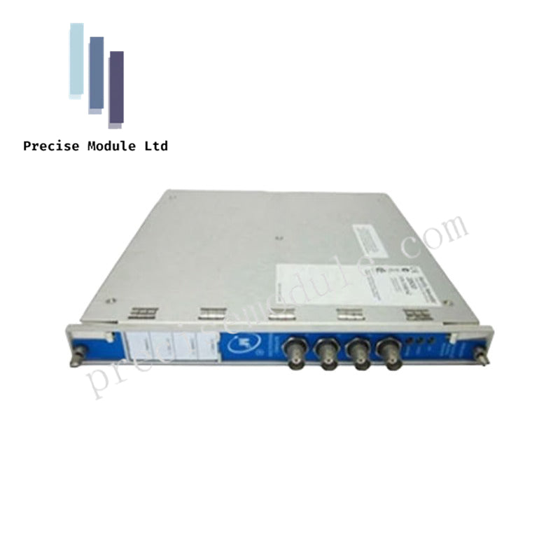
Bently Nevada 3500/40 143488-01 I/O Modules
Bently Nevada 3500/40 143488-01 I/O Modules
Manufacturer: Bently Nevada
Condition:in Stock
Product Type: I/O Modules
-
Product Origin: USA
Payment:T/T, Western Union
-
Weight: 550g
Shipping port: Shanghai/Yiwu/Shenzhen
Warranty: 12 months
Share
Bently Nevada 3500/40 143488-01 I/O Modules
The Bently Nevada 3500/40, also cataloged as the 143488-01 I/O Module, operates as a dedicated hardware component for signal routing and transducer termination within the 3500 Machinery Protection System platform.
Hardware Specifications
| Parameter | Specification |
|---|---|
| Model | 3500/40 (143488-01) |
| Brand | Bently Nevada |
| Origin | USA |
| Weight | 0.55 kg |
| Dimensions | 24.1 x 2.44 x 9.91 cm |
| Operating Temp | -30 deg C to +65 deg C (-22 deg F to +150 deg F) |
| Power Consumption | 7.7 Watts typical |
| Number of Channels | 4 channels |
| Inputs | Proximity transducers, accelerometers, velocity transducers |
| Signal Response | 0.1 Hz to 4.0 kHz (measurement dependent) |
| Recorder Outputs | +4 to +20 mA or 0 to +10 Vdc |
| A/D Conversion | 12-bit resolution |
Rotor Dynamics and Gap Voltage Validation
Operating within the framework of machinery protection architecture, this I/O module interfaces directly with multi-type vibration transducers to route raw signals to the associated front monitor module. The internal circuitry manages probe scaling and maintains strict signal conditioning targets across all four input channels. Signal integrity is preserved through robust shielding and backplane routing, suppressing electrical cross-talk and supporting precise evaluation of radial vibration, thrust position, eccentricity, differential expansion, and REBAM.
Frequently Asked Questions
Q: Can the 143488-01 I/O module be replaced without powering down the entire 3500 rack?
A: Yes, rear I/O modules support hot-insertion and removal when executed in coordination with front monitor slot protocols, provided proper safety measures for live industrial maintenance are followed.
Q: How are transducer signals terminated and protected against noise interference?
A: Termination is handled directly via dedicated terminal blocks on the module, utilizing standard shielding practices to ground incoming signal cables and prevent electromagnetic interference.
Field Installation Guidelines
Physical Placement: Mount the module into the designated rear slot directly aligned with its corresponding 3500/40M front monitor module within the rack frame.
Wiring and Grounding: Terminate all transducer cables securely to the module's connectors while ensuring shield drain wires are properly grounded to mitigate noise.
Verification: Check signal response parameters and confirm secure mechanical latching prior to powering the instrument rack.
Hot Tags :


- Choosing a selection results in a full page refresh.
- Opens in a new window.