


Bently Nevada
📢 100% genuine, extensive in-stock inventory, fast shipping!
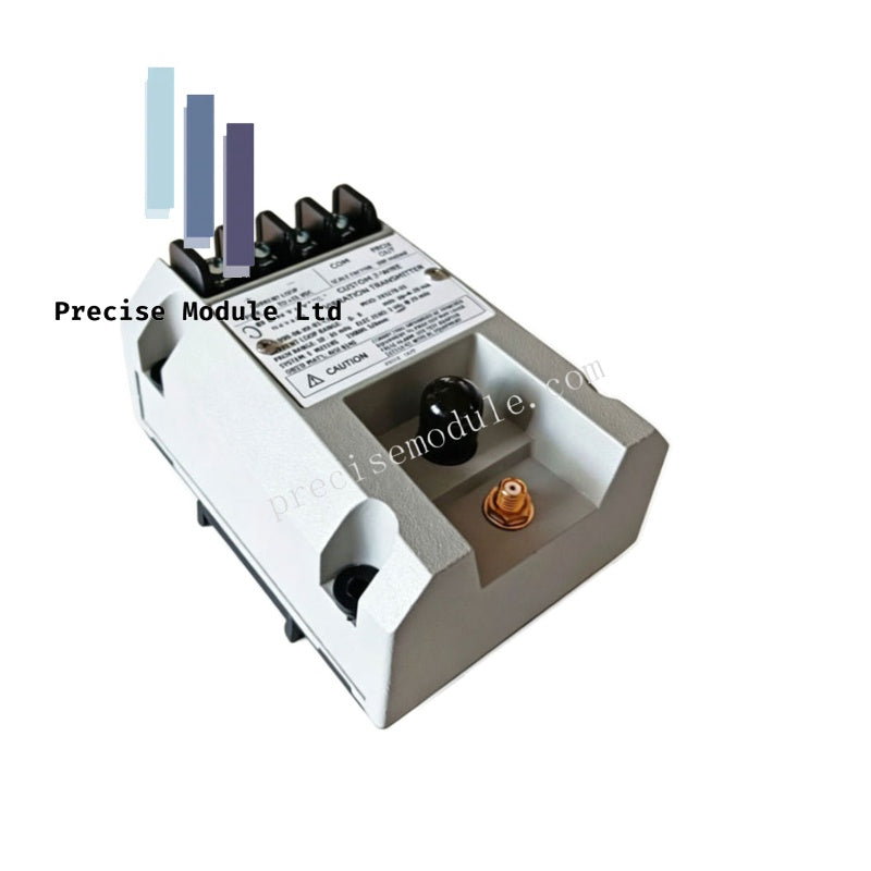
Bently Nevada 990-04-50-01-CN 990 Vibration Transmitter
Bently Nevada 990-04-50-01-CN 990 Vibration Transmitter
Manufacturer: Bently Nevada
Condition:in Stock
Product Type: Vibration Transmitter
-
Product Origin: USA
Payment:T/T, Western Union
-
Weight: 440g
Shipping port: Shanghai/Yiwu/Shenzhen
Warranty: 12 months
Share
Bently Nevada 990-04-50-01-CN 990 Vibration Transmitter
The Bently Nevada 990-04-50-01-CN, also cataloged as the 990 Vibration Transmitter, operates as a dedicated hardware component for radial vibration monitoring within industrial machinery control systems. Configured for proximity probe interfacing, the device transforms raw radio-frequency eddy-current signals from a 3300 NSv sensor into a linear 4-20 mA loop-powered output representing dynamic peak-to-peak vibration amplitude.
Hardware Specifications
| Parameter | Specification |
|---|---|
| Model | 990-04-50-01-CN |
| Brand | Bently Nevada |
| Origin | USA |
| Weight | 0.44 kg |
| Dimensions | 10 x 7.5 x 5.6 cm |
| Operating Temp | -40 deg C to +85 deg C (standard transmitter exposure rating) |
| Power Consumption | Loop-powered, 24 VDC nominal (requires 4-20 mA loop supply) |
| Full-scale Option | 0-4 mils pp (0-100 um pp) |
| System Length Option | 5.0 meters (16.4 feet) |
| Mounting Option | 35 mm DIN rail clips |
| Measurement Range | +/- 50 mils (1.27 mm) |
| Frequency Range | DC to 10 kHz |
| Tariff Code | 8537101190 |
Machinery Monitoring & Eddy-Current Probe Scaling
The Bently Nevada 990-04-50-01-CN integrates the functionality of a traditional proximity sensor and transmitter into a singular potted enclosure. Internal drive circuits energize the connected 3300 NSv eddy-current probe, establishing an electromagnetic field near the target shaft surface. To ensure correct eddy-current probe scaling across the static measurement range of +/- 50 mils (1.27 mm), the device tracks variations in RF impedance. As the shaft vibrates, the high-frequency AC component is conditioned directly into a calibrated 4-20 mA current loop proportional to peak-to-peak displacement. For diagnostic validation, the raw gap voltage and dynamic vibration signal are accessible via the coaxial connector and the non-isolated PROX OUT / COM terminals. The integrated Not OK / Signal Defeat circuit monitors the integrity of this physical cable connection, clamping the loop output to prevent false high-signal trips or alarms in the event of an eddy-current probe breakdown or a disconnected extension line.
Frequently Asked Questions
Q: How can the dynamic response and loop output of the 990-04-50-01-CN be verified in the field?
A: The transmitter features a dedicated Test Input pin. By injecting a variable AC signal from an external function generator into this terminal, personnel can simulate dynamic shaft vibration to verify loop-signal precision across the 4-20 mA full-scale spectrum.
Q: Does adjusting the zero calibration setting on this transmitter skew the full-scale span limit?
A: No. The 990-04-50-01-CN utilizes non-interacting external zero and span potentiometers located under the transmitter label, allowing individual parameter calibration without loop interaction.
Field Installation Guidelines
- Mounting Configurations: Secure the transmitter utilizing the factory-configured 35 mm DIN rail clips. The potted construction allows deployment in high-humidity zones up to 100% condensing, but protection from direct liquid spray or standing water is required.
- System Length Calibration: The transmitter must match the selected 5.0 meters system length option. Altering, splicing, or trimming the length of the 3300 NSv extension cable will invalidate the factory calibration matrix and introduce significant measurement linearity errors.
- Potentiometer Adjustments: Zero and span adjustments must be executed via the non-interacting potentiometers located beneath the transmitter label. Use a non-conductive tuning tool to prevent electrical shorts or signal fluctuations during field calibration.
- Shield Isolation: Maintain shield continuity through the probe-to-extension connection using insulation sleeves. Ground the overall cable shield exclusively at a single point inside the receiver control panel to suppress common-mode electromagnetic noise.
Hot Tags :


- Choosing a selection results in a full page refresh.
- Opens in a new window.