


Bently Nevada
📢 100% genuine, extensive in-stock inventory, fast shipping!
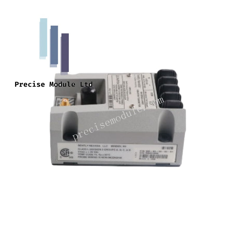
Bently Nevada 991-06-50-01-00 991 Series Thrust Transmitter
Bently Nevada 991-06-50-01-00 991 Series Thrust Transmitter
Manufacturer: Bently Nevada
Condition:in Stock
Product Type: Thrust Transmitter
-
Product Origin: USA
Payment:T/T, Western Union
-
Weight: 440g
Shipping port: Shanghai/Yiwu/Shenzhen
Warranty: 12 months
Share
Bently Nevada 991-06-50-01-00 991 Series Thrust Transmitter
The Bently Nevada 991-06-50-01-00, also cataloged as the 991 Thrust Transmitter, operates as a dedicated hardware component for axial displacement monitoring within industrial machinery control systems. Configured for proximity probe interfacing, the device transforms raw radio-frequency eddy-current signals from a 3300 NSv sensor into a linear 4-20 mA loop-powered output representing dynamic shaft position.
Hardware Specifications
| Parameter | Specification |
|---|---|
| Model | 991-06-50-01-00 |
| Brand | Bently Nevada |
| Origin | USA |
| Weight | 0.44 kg |
| Dimensions | 7.4 x 6 x 10 cm |
| Operating Temp | -40 deg C to +85 deg C (standard transmitter exposure rating) |
| Power Consumption | Loop-powered, 24 VDC nominal (requires 4-20 mA loop supply) |
| Maximum Loop Resistance | 1000 ohms including cable at 35 VDC |
| Current Limiting | 23 mA typical |
| Minimum Target Size | 9.5 mm (0.375 in) diameter |
| Input Compatibility | 3300 NSv proximity probe and matching extension cable (5 m or 7 m) |
| Output Signal | 4-20 mA DC proportional to axial displacement |
| Tariff Code | 8537101190 |
Machinery Monitoring & Eddy-Current Probe Scaling
The Bently Nevada 991-06-50-01-00 integrates the functionality of a traditional proximity sensor and transmitter into a singular potted enclosure. Internal drive circuits energize the connected 3300 NSv eddy-current probe, establishing an electromagnetic field near the target shaft surface. To ensure correct eddy-current probe scaling, the minimum target size must be a diameter of 9.5 mm (0.375 in). As the shaft shifts axially, the change in gap voltage is conditioned directly into a calibrated 4-20 mA current loop. For diagnostic validation, the raw gap voltage (-10 VDC target range) is accessible via the coaxial connector and the PROX OUT terminal. The integrated Not OK / Signal Defeat circuit monitors the integrity of this physical cable connection, clamping the loop output to prevent false high-signal trips or alarms in the event of an eddy-current probe breakdown or a disconnected extension line.
Frequently Asked Questions
Q: What is the absolute maximum loop resistance allowed for the 991-06-50-01-00 signal loop?
A: The maximum loop resistance is 1000 ohms, which includes the resistance of the interconnecting field cable when operating at a loop voltage of 35 VDC.
Q: How can the loop output of the 991-06-50-01-00 be verified without physically moving the machine shaft?
A: The transmitter features a dedicated Test Input pin. By applying a variable external DC voltage source to this terminal, personnel can simulate gap changes to verify zero, span, and overall loop-signal precision across the 4-20 mA spectrum.
Q: Does adjusting the zero setting on this transmitter alter the span setting?
A: No. The 991-06-50-01-00 utilizes non-interacting external zero and span adjustments under the transmitter label, allowing individual parameter calibration without loop interaction.
Field Installation Guidelines
- Mounting Configurations: Secure the transmitter utilizing standard DIN-rail clips or direct bulkhead mounting screws. The potted construction allows deployment in high-humidity zones up to 100% condensing, but protection from direct liquid spray is required.
- System Length Calibration: The transmitter must match the selected system length option (5 m or 7 m). Altering or trimming the length of the 3300 NSv extension cable will invalidate the factory eddy-current calibration and introduce measurement linearity errors.
- Potentiometer Adjustments: Zero and span adjustments must be executed via the non-interacting potentiometers located beneath the transmitter label. Use a non-conductive tuning tool to prevent electrical shorts or signal fluctuations during field calibration.
- Shield Isolation: Maintain shield continuity through the probe-to-extension connection using insulation sleeves. Ground the overall cable shield exclusively at a single point inside the receiver control panel to suppress common-mode electromagnetic noise.
Hot Tags :


- Choosing a selection results in a full page refresh.
- Opens in a new window.