


Bently Nevada
📢 100% genuine, extensive in-stock inventory, fast shipping!
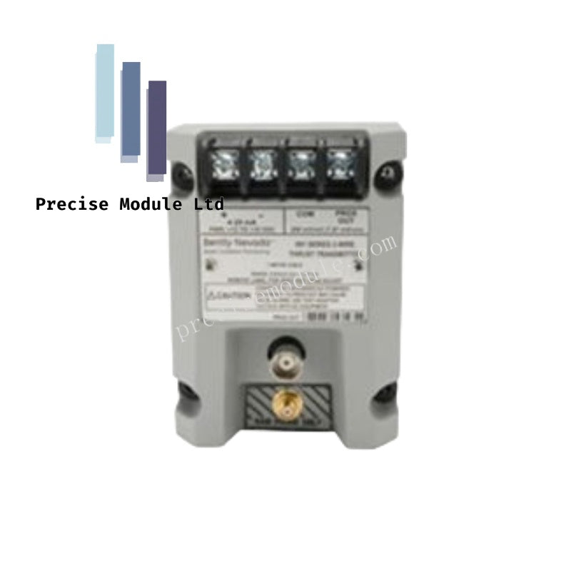
Bently Nevada P3403893-0351 Wire Vibration Transmitter
Bently Nevada P3403893-0351 Wire Vibration Transmitter
Manufacturer: Bently Nevada
Condition:in Stock
Product Type: Wire Vibration Transmitter
-
Product Origin: USA
Payment:T/T, Western Union
-
Weight: 550g
Shipping port: Shanghai/Yiwu/Shenzhen
Warranty: 12 months
Share
Bently Nevada P3403893-0351 Wire Vibration Transmitter
Configured for seismic vibration monitoring within rotating machinery protection systems, the Bently Nevada P3403893-0351 (P3403893-0351 Wire Vibration Transmitter) provides direct physical/electrical execution. This transducer assembly converts structural mechanical velocity into a conditioned output signal compatible with existing monitoring instrumentation, facilitating local seismic data acquisition without the necessity for external signal conditioning modules.
Suffix Breakdown & Model Matrix
| Option Code | Parameter | Description / Standard Specifications |
|---|---|---|
| P3403893-0351 | Part Number | Standard base configuration for seismic velocity monitoring |
| Transducer Type | Sensing Element | Piezoelectric seismic acceleration sensor with internal integration |
| Signal Output | Proportional Data | 4-20 mA loop-powered velocity signal |
| Housing | Material | Stainless steel, corrosion-resistant, industrial grade |
Hardware Specifications
| Parameter | Specification |
|---|---|
| Model | P3403893-0351 |
| Brand | Bently Nevada |
| Origin | USA |
| Weight | 0.55 kg |
| Dimensions | 7.5 x 6 x 10 cm |
| Operating Temp | -40 deg C to +85 deg C |
| Power Consumption | 24 VDC nominal (12 to 32 VDC range) |
| Frequency Range | 10 Hz to 1 kHz (standard industrial band) |
| Mounting | 1/4-28 UNF stud or magnetic base |
Bently Nevada Mechanical Monitoring & TSI Characteristics
The P3403893-0351 facilitates precise rotor dynamics and casing vibration analysis by ensuring the piezoelectric sensing element maintains linearity across the specified frequency spectrum. Unlike proximity-based eddy-current probe scaling, which targets gap voltage validation at -10 VDC, this seismic transmitter utilizes a dedicated internal integrator to translate acceleration inputs into velocity-based outputs. Users must ensure that mounting surfaces are prepared to a flat finish to prevent signal attenuation or phase shifts. Proper shielding of the output cabling is mandatory to mitigate cross-talk suppression issues in environments with high electromagnetic interference, ensuring the integrity of the raw seismic signal before conversion to the 4-20 mA loop current.
Frequently Asked Questions
Q: Does the P3403893-0351 support live connection to the 4-20 mA loop?
A: Yes, the unit is loop-powered. However, ensure that the power supply voltage does not exceed 32 VDC to prevent damage to the internal signal conditioning circuitry.
Q: How does the internal integration affect the output frequency response?
A: The internal circuit provides a true velocity output proportional to the seismic input within the 10 Hz to 1 kHz range. Signals exceeding these bounds may exhibit non-linear attenuation depending on the mounting coupling.
Field Installation Guidelines
- Mounting Integrity: Utilize the designated mounting stud to secure the transmitter directly to the machine casing. Ensure the interface is free of paint, scale, or debris to maintain a mechanical impedance path for high-frequency vibrations.
- Cabling and Grounding: Use shielded twisted-pair instrumentation cable. Terminate the shield at the common ground point at the receiver end only to prevent ground loops.
- Loop Verification: Prior to final commissioning, verify that the 24 VDC loop voltage is present and that the current output is within the 4 mA (zero vibration) to 20 mA (full-scale) range.
- Orientation: Mount the device in the axis of interest (typically horizontal or vertical) to capture the intended vibration vectors as per the machine OEM requirements.
Hot Tags :


- Choosing a selection results in a full page refresh.
- Opens in a new window.