


Bently Nevada
📢 100% genuine, extensive in-stock inventory, fast shipping!
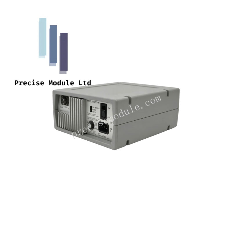
Bently Nevada TK15 80917-01 Keyphasor Conditioner and Power Supply
Bently Nevada TK15 80917-01 Keyphasor Conditioner and Power Supply
Manufacturer: Bently Nevada
Condition:in Stock
Product Type: Keyphasor Conditioner and Power Supply
-
Product Origin: USA
Payment:T/T, Western Union
-
Weight: 1000g
Shipping port: Shanghai/Yiwu/Shenzhen
Warranty: 12 months
Share
Bently Nevada TK15 80917-01 Keyphasor Conditioner and Power Supply
The Bently Nevada TK15 80917-01, also cataloged as the TK15 Keyphasor Conditioner and Power Supply, operates as a dedicated hardware component for transducer power distribution and signal conditioning within portable machinery diagnostic networks.
Hardware Specifications
| Parameter | Specification |
|---|---|
| Model | 80917-01 |
| Brand | Bently Nevada |
| Origin | USA |
| Weight | 1.00 kg |
| Dimensions | 10.0 x 10.0 x 50.0 cm |
| Operating Temp | 0 deg C to +50 deg C (Standard industrial portable rating) |
| Power Consumption | Factory fused for 115 VAC operation; alternative 230 VAC fuse included |
| Channels | 2 independent conditioning channels |
| Supported Signals | Proximity probe inputs, Keyphasor triggers, pre-recorded transducer signals |
| Included Accessories | 1 TK15 unit, 1 User Guide, 1 Power Cord, 1 230 VAC operational fuse |
Rotor Dynamics Phase Validation & Cross-Talk Suppression
The portable conditioning architecture employs active electrical filtering to handle incoming transducer signals without altering critical phase data. In rotor dynamics analysis, processing raw eddy-current probe inputs requires exact edge-detection thresholds to establish the Keyphasor phase reference signal. The internal power supply circuit routes stable, isolated DC voltage to external proximity transducers, maintaining line regulation metrics that isolate low-amplitude vibration signals from power frequency interference. Active cross-talk suppression between the two independent channels guarantees that synchronous timing signals do not bleed into adjacent dynamic data paths.
Frequently Asked Questions
Q: How must the internal fuses be managed when switching between 115 VAC and 230 VAC line voltages?
A: The instrument ships with the 115 VAC operational fuse physically installed in the power inlet module. For 230 VAC utility power, the operator must manually extract the fuse drawer, remove the 115 VAC fuse, and replace it with the dedicated 230 VAC fuse supplied in the packaging accessory kit prior to energizing the circuit.
Q: Can this instrument condition analog signals playback from data recorders?
A: Yes. The dual-channel hardware architecture accepts both live field transducer connections and pre-recorded analog transducer signals. It standardizes the voltage offsets and impedance profiles for safe interfacing with downstream portable machinery diagnostic analyzers.
Field Installation Guidelines
- Line Voltage Verification: Before connecting the AC power cord, confirm the rear voltage selector switch position or internal fuse configuration matches the local utility grid (115 VAC versus 230 VAC) to avoid catastrophic transformer failure.
- Coaxial Shield Integrity: Ensure all BNC signal cables connected to the input and output channels retain 100% shield coverage. The instrument housing must maintain a single-point connection to earth ground via the third pin of the power cord to prevent common-mode noise from corrupting the phase markers.
- Enclosure Ventilation: When deploying the unit as a temporary benchtop asset during diagnostic routines, maintain a minimum clear boundary space of 50 mm around the outer casing perimeter to permit unimpeded passive thermal dissipation.


- Choosing a selection results in a full page refresh.
- Opens in a new window.