


Honeywell
📢 100% genuine, extensive in-stock inventory, fast shipping!
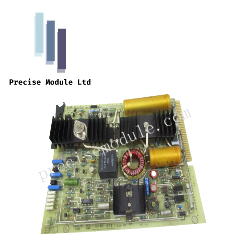
Honeywell 30731808-001 Regulator Card Board
Honeywell 30731808-001 Regulator Card Board
Manufacturer: Honeywell
-
Product No.: 30731808-001
Condition:in Stock
Product Type: Regulator Card Board
-
Product Origin: USA
Payment:T/T, Western Union
-
Weight: 190g
Shipping port: Shanghai/Yiwu/Shenzhen
Warranty: 12 months
Share
Honeywell 30731808-001 Regulator Card Board
The Honeywell 30731808-001 serves as the primary 30731808-001 Regulator Card Board utilized to execute regulated DC power conversion and distribution across Honeywell control system platforms. The board accepts a +24 VDC backplane supply and generates regulated +5 VDC, +12 VDC, and -12 VDC outputs for controller, memory, and associated chassis-mounted electronic assemblies.
Hardware Specifications
| Parameter | Specification |
|---|---|
| Model | 30731808-001 |
| Brand | Honeywell |
| Origin | USA |
| Product Type | Regulator Card Board |
| Input Voltage | +24 VDC from system backplane |
| Output Voltage Rail 1 | +5 VDC regulated |
| Output Voltage Rail 2 | +12 VDC regulated |
| Output Voltage Rail 3 | -12 VDC regulated |
| Function | Power regulation and distribution |
| Supported Assemblies | Controller and memory-related chassis modules |
| Overload Protection | Removable fuses |
| Diagnostics | Front-panel test sockets and fault reporting |
| Dimensions | 3.7 cm x 14.0 cm x 13.6 cm |
| Weight | Approximately 0.79 kg |
| Operating Temp | 0 deg C to 60 deg C |
| PCB Flammability Rating | UL 94V-0 |
Power Rail Regulation and Distribution Characteristics
The regulator card converts an incoming +24 VDC chassis supply into three regulated voltage rails used by associated control system electronics. Output regulation supports the distribution of stable DC operating voltages to connected controller and memory assemblies through the system backplane.
Integrated fault communication circuitry allows detected regulated-voltage abnormalities to be communicated to adjacent cards within the card file. Front-panel test points provide direct access for maintenance verification, voltage measurement, and calibration activities without disturbing installed wiring or associated modules.
Frequently Asked Questions
Q: Which regulated voltages are generated by the board?
A: The board provides regulated +5 VDC, +12 VDC, and -12 VDC output rails derived from a +24 VDC backplane supply.
Q: How can output voltages be verified during maintenance?
A: The board includes front-panel test sockets that permit direct voltage measurement and calibration checks using standard test instruments.
Q: What protective features are incorporated into the card design?
A: The board includes removable fuse protection. Documentation indicates that some hardware revisions utilize three fuses, while later revisions utilize two fuses.
Field Installation Guidelines
-
Verify that chassis backplane power conforms to the specified +24 VDC input requirement before installation.
-
Fully seat the card into the designated slot and confirm correct connector engagement.
-
De-energize the card file before replacing fuses unless plant maintenance procedures explicitly permit energized servicing.
-
Use the provided test points when verifying regulated output voltages.
-
Inspect fuse condition whenever abnormal voltage readings or power distribution faults are detected.
-
Maintain unobstructed airflow around the installed card to support normal thermal dissipation.
-
Ensure card guides and retaining hardware are properly secured after installation.
-
Confirm successful power rail operation before returning dependent controller or memory assemblies to service.
Hot Tags :


- Choosing a selection results in a full page refresh.
- Opens in a new window.