


Honeywell
📢 100% genuine, extensive in-stock inventory, fast shipping!
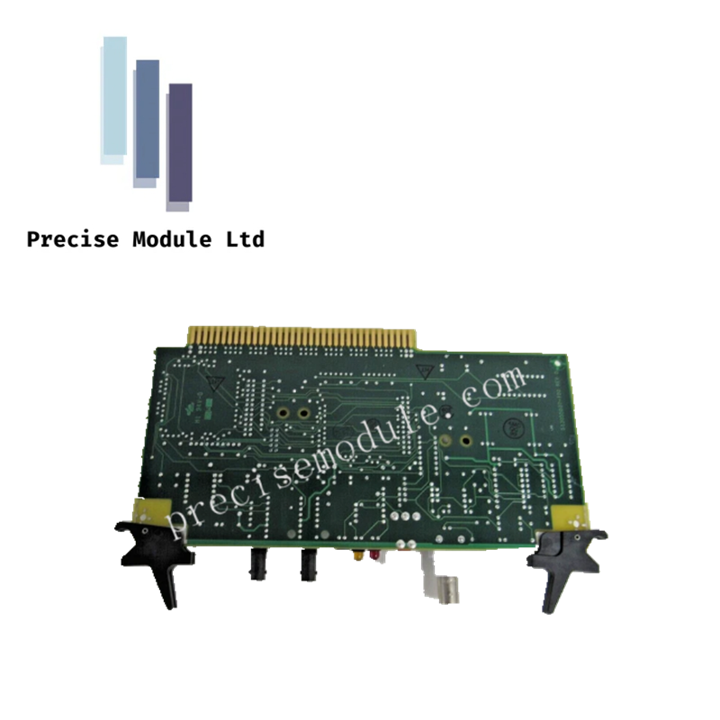
Honeywell 51305517-100 LCNP4 Control Board
Honeywell 51305517-100 LCNP4 Control Board
Manufacturer: Honeywell
-
Product No.: 51305517-100
Condition:in Stock
Product Type: Control Board
-
Product Origin: USA
Payment:T/T, Western Union
-
Weight: 1000g
Shipping port: Shanghai/Yiwu/Shenzhen
Warranty: 12 months
Share
Honeywell 51305517-100 LCNP4 Control Board
The Honeywell 51305517-100, also cataloged as the LCNP4 Control Board, operates as a modular PCB assembly for communication and processing tasks within Honeywell TDC3000, TPS, and PKS control architectures.
Hardware Specifications
| Parameter | Specification |
|---|---|
| Model | 51305517-100 |
| Brand | Honeywell |
| Origin | U.S.A |
| Weight | ~360 g |
| Dimensions | Compact PCB form factor |
| Operating Temp | Industrial ambient range |
| Storage Temp | Industrial ambient range |
| Power Consumption | Supplied via system backplane |
| Function | Local Control Network (LCN) processing and communication |
| Build Standard | M1 94V-0 compliant PCB |
| Compatibility | Associated with assemblies such as 51403299 |
4-20 mA HART Loop Protocol
The LCNP4 board integrates seamlessly into Honeywell distributed control environments, supporting deterministic communication across the Local Control Network. Channel-to-channel isolation is preserved through PCB design, while galvanic separation ensures safe interaction between user circuits and system logic. Cold junction compensation (CJC) techniques stabilize signal processing under varying ambient conditions.
Frequently Asked Questions
Q: Can the LCNP4 be hot-swapped in a live rack? A: No, insertion or removal under power is not recommended due to potential bus disturbances.
Q: How is redundancy achieved with LCNP4 boards? A: Redundancy is managed at the system level; the board itself does not provide internal failover switching.
Q: Does the LCNP4 require calibration? A: No, it is a communication and processing board; calibration applies to connected field devices, not the board itself.
Field Installation Guidelines
- Insert the board into the designated slot with power isolated.
- Ensure backplane connectors are fully seated to maintain communication integrity.
- Route cabling away from high-voltage conductors to minimize EMI.
- Verify grounding of the control cabinet to prevent noise coupling.
- Inspect PCB for mechanical wear or contamination before commissioning.
Hot Tags :


- Choosing a selection results in a full page refresh.
- Opens in a new window.